Large Signal Phenomena using the MXO5 - Sequential Trigger Measurement Setup
- Benjamin Dannan

- Nov 27, 2024
- 3 min read
Updated: Sep 16, 2025

When dealing with power distribution networks (PDN), distinguishing between large and small signal phenomena is essential for accurate analysis and validation. This is why it is important to validate a design by doing both small and large signal measurements. This article explores how to effectively capture large signal behaviors using the MXO5 through a sequential trigger measurement setup.
The Importance of Signal Integrity Measurement Equipment
To get started on your signal measurement, we recommend that you have access to high-quality measurement equipment. This initial step is crucial as it lays the groundwork for obtaining precise and reliable measurement results, setting the stage for sophisticated signal analysis.
This is the list of tools and instruments we used and recommend:
Picotest 160A, 0.8Vout PDN Validation Demo
ZPR40 power rail probe

Understanding Small vs. Large Signal Phenomena
Small signals are characterized by minor signal fluctuations around a nominal DC operating point. Testing small signals typically focuses on analyzing parameters such as impedance and Power Supply Rejection Ratio (PSRR) and generating Bode plots.
In contrast, large signals pertain to more dynamic phenomena such as transient responses, step reactions, and voltage droops, which occur when there is a decrease in voltage during a sudden increase in current. Testing for large signals involves examining transient behaviors and step responses and observing the large signal impedance, which can be performed using specialized tools like a Custom Picotest in-socket transient step load, a custom soldered down transient step load, a browser step load like the P2105A Probe Based Stepper (S10), or the Water-Cooled Head Stepper (S50).
Sequential Trigger Measurement Setup: A Detailed Approach
The sequential trigger measurement setup is a critical technique for capturing and analyzing large signal phenomena. This method involves several key steps:
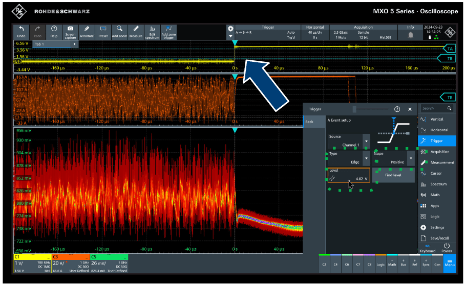
Step One, Trigger On: The process begins with selecting the sequence under the "Trigger On" setting.

Step Two, Setup A Trigger: Next, you must set up the first trigger. In this example, we selected the 'Edge' type and 'Positive' slope. Then we adjusted the trigger A level on the rising edge of CH1 where CH1 provides a sync edge to allow us to align to the start of a repeating sequence that is running on the step load.

Step Three, Setup B Trigger: We must set up a second trigger. For this example, we selected the 'Edge' type and 'Negative' slope and adjusted the trigger B level on the falling edge of CH3 where CH3 is the emulated current from the Picotest 160A step load.

With the MXO 5, you can trigger on a single trigger event or on a sequence of events. A trigger sequence consists of at least two event conditions and additional conditions defining when the trigger occurs.
The trigger sequence A → B → R, for example, consists of two subsequent events: A-trigger and B-trigger with optional B-trigger delay and count. In addition, an optional reset condition R can be configured: timeout or R-trigger condition. A-, B-, and R-triggers are configured in the same way.
In the capture below, we are showing an example of a large signal phenomenon, where on the 160A load dump, we see the power supply and PDN response from a 160A load dump from the Picotest load stepper. When the step load turns off, or in this case, goes from 160A to 0A, the VRM switch turns off, and we see the response from the energy stored in the inductors. Depending on the phase alignment of the load dump to the VRM's switching frequency, an infinite number of large signal responses can occur. This example shows that our voltage peak varies by around 52 mV.

You can watch the video directly below to see a recorded large signal phenomenon response using the sequential trigger on the MXO 5.
Conclusions and Wrap-Up
Validating power distribution networks requires a comprehensive approach that requires both large and small signal measurements. Issues such as ground loops can significantly impact measurements, so using a Common Mode Isolator like the J2115A or J2102B is also recommended to break the ground loop. Furthermore, it is important to validate the PDN design across multiple frequencies to assess the large signal response and cross-talk performance within the design. Tools like the Picotest Water-Cooler Head Stepper S50 or P2105A Probe-Based Stepper (S10) enable straightforward 'Go / no-Go' large signal testing, allowing precise and repeatable load current control. This capability is essential for characterizing and validating various aspects of the power rail, including PDN cross-talk, thermal performance, and electromagnetic interference. Finally, creating forced PDN responses with various patterns—whether pseudo-random, long dwell, sine, or pulse—enhances the thoroughness of the testing and validation process.
By integrating these methodologies with a great oscilloscope like the MXO5, engineers can ensure a robust analysis and optimization of power distribution networks, leading to more efficient and reliable electronic systems.


Comments