
The Challenge of Measuring a 40 uOhm (2000 Amp) PDN with a 2-Port Probe – How Much CMRR is Needed?
- Benjamin Dannan

- Feb 17, 2024
- 5 min read
Benjamin Dannan and Steve Sandler
Part 1 of 3
This article is the first part of a 3-part series focusing on the challenges of impedance measurement and PDN validation, including 2000 amp PDN and 2-port probe measurement techniques:
Part 2 - The Measurement Result!
Introduction
Most of us are aware of the ground loop error in the 2-port measurement. Most of us are also aware that we need to introduce a ground loop isolator to correct this error. If not, we’ve published plenty on the subject. But how much CMRR measurement do you need to add? How does the use of a probe impact this high CMRR requirement?
Rest assured, this impedance measurement can be successfully performed, as shown in Figure 1, and we’ll show you how to determine how much CMRR it takes in this blog.
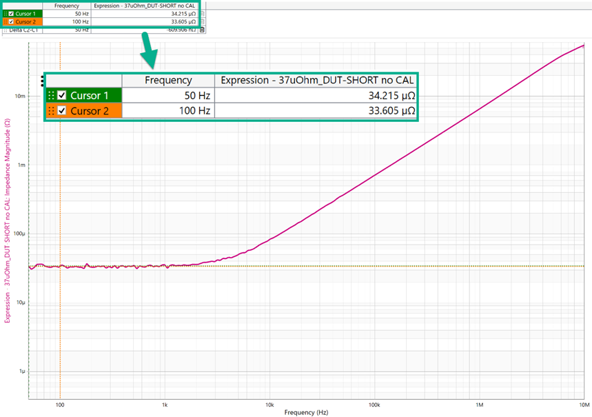
Figure 1 – Depiction of 37 µΩ Known DUT 2-port Shunt Through Impedance Measurement.
Companies like Intel, Nvidia, AMD, Qualcomm, and Broadcom are putting more cores on a single die. Ampere is an excellent example where they have designed a cloud processor solution with 192 cores on a single die. While 2000 Amps may seem excessive, the power demands of data centers, supercomputing, and AI have already surpassed this number. Without adding other considerations on the thermal design or PDN validation, let’s focus on what is required to measure a 2000 Amp PDN.
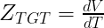
Measuring a 2000 Amp PDN with a 2-port probe or even with two 1-port probes is not intuitive or even trivial. To effectively conduct a 2-port probe measurement of a 2000 Amp PDN, it is important first to understand the desired impedance to be measured to support 2000 Amps. With reference to EQ(1), if it is assumed that a 0.8V power domain has an 80 mV peak-to-peak ripple spec, then with a 2000 Amp step load, the target impedance (ZTGT) is 40 µΩ.
EQ(1)
The Ground Loop Error
Why is CMR Necessary for Mitigating Ground Loop Errors?
With the understanding of the ZTGT, efforts can be made to understand the requirements to make a measurement at the desired 40 µΩ. It quickly becomes clear that the common mode rejection ratio (CMRR) is an important figure of merit to mitigate ground loop error for successful low impedance measurements into the micro-ohms associated with the two-port probe measurement. This method is well-published, so this discussion will not include details about the process.
What Does Ground Loop Error Look Like in a 2-Port Setup?
Figure 1 shows a 2-port impedance measurement setup using 1-meter PDN cables for a 40 µΩ Device Under Test (DUT). The ground loop error is clearly visible, and the error from this is shown in Figure 2.

Figure 2 – 40 µΩ DUT Impedance Measurement Setup with 1-meter PDN Cables.

Figure 3 - 40 µΩ DUT Impedance Measurement Setup with 1-meter PDN Cables.
What Components actually Make up Ground Loop Resistance?
The ground loop resistance is the parallel equivalent of the two cables connecting the VNA to the DUT. In this instance, the two cables are identical, as are the probe ground pins. Hence, the resistance of a single cable and probe pin is twice this measured value.
EQ(2)

The return resistance is the sum of the cable shield and pin resistance.
EQ(3)

By substitution
EQ(4)
Solving for the measured value and adding the DUT results in
EQ(5)

This clarifies that the ground loop comprises two parts, the cable and the pin. Each contributes a resistance to the ground loop error.
Can Calibration Remove Ground Loop Errors?
A common mistake is to use calibration to remove the ground loop error. The calibration will subtract the constant value of R_measured from the result, which theoretically provides the correct measurement.
EQ(6)

This method doesn’t work because the value of K is a constant, but the resistance value of the cable and pin is not. Bending the cable or adding compression to the pin will slightly change the ground resistance. The ground resistance of BNC connectors, used on many VNAs, also varies. However, this small change is of the same magnitude as the DUT, while the cable plus pin resistance is many orders of magnitude larger than the DUT.
This method attempts to take the difference between two very large numbers to obtain a very small result. This is often unsuccessful.
Introducing a Ground Isolator
The introduction of a ground isolator changes the equation to
EQ(7)

In this case, the ground resistance is first divided by the CMRR of the isolator, significantly reducing the sensitivity to small changes in the ground loop resistance.
A transformer isolator limits this CMRR at low frequency, while solid-state isolators do not. On the other hand, transformers typically work to a higher frequency than a solid-state isolator, presenting a tradeoff. The question is how much isolation is required for reasonable measurement, such as when performing a CMRR measurement or 2-port probe measurement.
EQ(8)

EQ(9)

EQ(10)
Assuming a tolerance for a 10% ground loop error in our 40uOhm impedance measurement, the error term must be less than 40µΩ.
EQ(11)
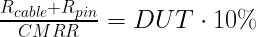
EQ(12)
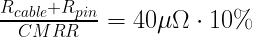
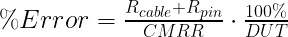
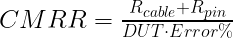
This allows us to solve for the required isolator CMRR to perform this measurement effectively.
EQ(13)
The shield resistance of a 1-meter PDN cable is approximately 15mΩ. The resistance of the Picotest P2104A pin is also typically about 15mΩ, although contact pressure can vary significantly, affecting tolerance.
EQ(14)

EQ(15)

The minimum CMRR to make the measurement is 77.5dB at low frequency, highlighting the high CMRR requirement.
Reducing the Ground Loop Error with CMRR
To demonstrate the CMRR measurement requirements, an ideal, parameterized, op-Amp is inserted into the simulation setup shown in Figure 1 and is depicted in Figure 3. The results for a 2-port shunt measurement with 1-meter PDN cables and an ideal op-amp is shown in Figure 4. The ideal op-amp acts as the ground loop isolator. The CMRR for an op-amp with 57dB and 77.5dB is shown versus a result with no CMRR. The result with 57dB of CMRR demonstrates another Picotest product, the J2113A amplifier.

Figure 4 – 40 µΩ Impedance Measurement Setup with 1-meter PDN cables and Ideal Op Amp.

Figure 5 - 40 uΩ DUT Impedance Measurement Setup with 1-meter PDN Cables with CMRR Variation.
As shown by Figure 4, an uncalibrated error of 7.4% in the impedance measurement for our 40 µΩ DUT is achieved when the high CMRR requirement is met with 77.5dB. However, as shown in Figure 4, when CMRR is equal to 57dB, the ground loop error results in an uncalibrated error nearing 100%. This again emphasizes the earlier point that measuring a 2000 Amp PDN at 40 µΩ is not easy or intuitive. Calibration can then be used to further improve this accuracy.
Follow this LINK to check out part 2 of this blog discussion, demonstrating how to measure a 40 uΩ DUT using a 2-port probe measurement.
References
Picotest J2114A High CMRR Isolation Amplifier - Ground Loop Breaker | Signal Edge Solution (signaledgesolutions.com)
S. M. Sandler, “How to measure ultra-low impedance (100uOhm and lower) PDNs,” EDI CON, October 2018.
A. K. Davis, S. M. Sandler, “The 2-Port Shunt-Thru Measurement and the Inherent Ground Loop,” EDI CON, October 2018.
Picotest P2102A 2-port Probe - Picotest P2102A 2-Port Probe | Signal Edge Solution (signaledgesolutions.com)
Picotest P2104A - Picotest P2104A 1-Port Transmission Line PDN Probe | Signal Edge Solution (signaledgesolutions.com)
Picotest PDN Cable - Picotest PDN Cable | Signal Edge Solution (signaledgesolutions.com)
Picotest J2113A Semi-Floating Differential Amplifier - Picotest J2113A Semi-Floating Differential Amplifier - Ground Loop Breaker | Signal Edge Solution (signaledgesolutions.com)
Omicron Bode 100 Vector Network Analyzer - Omicron Bode 100 Vector Network Analyzer | Signal Edge Solution (signaledgesolutions.com)


Comments