
Mitigating PDN Crosstalk and Ground Loops in AI and Data Center ASICs
- Benjamin Dannan

- Mar 19
- 6 min read

In the world of high-speed design for AI, data center, and hyperscaler applications, the power distribution network (PDN) is the lifeblood of electronic devices, delivering even higher power across sophisticated circuitry. As ASICs and other complex GPU chips increase in density and power demand, the number of power domains on a single chip, package, and PCB is skyrocketing. This trend, while necessary for higher performance, introduces a significant and often overlooked challenge: PDN crosstalk, which can also impact signal integrity.
Crosstalk is the unintended interference that occurs when electromagnetic energy from one signal (aggressor) couples onto an adjacent signal (victim). In the PDN, this interference is particularly problematic as it can happen between any two conductors, including PDN-to-PDN, leading to degraded performance in sensitive circuits like phase-locked loops (PLLs), clocks, and radio frequency (RF) signals by introducing destructive jitter and noise. For instance, a complex platform like the AMD Versal VPK180 evaluation board features 23 power domains, illustrating the massive potential for crosstalk issues in modern, high-speed electronics.
Measuring and Analyzing PDN Crosstalk in the Time and Frequency Domains
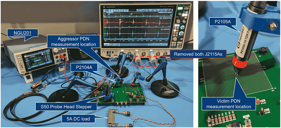
To truly grasp the impact of this phenomenon, we turned to measurement and analysis. We can demonstrate the effects of PDN crosstalk using the Picotest S50 Demo Board. These measurements required capturing multiple non-synchronized signals using the MXO5. These trigger settings and how to setup the zone trigger are discussed here.
In this multi-channel MXO5 oscilloscope measurement setup with the R&S NGL202, shown in Figure 1, we used the P2104A to measure the PDN aggressor response near the output of a 4-phase 100A VRM, while the P2105A measures the victim PDN response at the BGA location on the PCB. These P2104 and P2105 probes ensure low-noise power integrity measurements. A Picotest water-cooled 50A stepper load is used to excite a load on the aggressor PDN.
With a 5A DC load on the victim PDN and the aggressor off, the victim PDN showed a baseline voltage noise of 170.52 mVpp. This result is shown in Figure 2.
However, as shown in Figure 3, when a 50A pulsed load from the Picotest S50 was applied to the aggressor PDN, the victim PDN voltage noise increases significantly by 228.84 mVpp, reaching 317.13 mVpp. This substantial increase highlights the detrimental impact of PDN crosstalk on voltage stability, largely due to coupling across the PCB.
The influence of crosstalk is not limited to the time domain; As shown in Figure 4, it profoundly affects the frequency domain as well. Analyzing the noise spectrum with the MXO5 and the 50A pulsed load reveals a notable 10 dB to 30 dB increase in noise from 100 kHz to 50 MHz experienced by the victim PDN. This increase across a wide frequency band underscores the pervasive nature of PDN crosstalk in high-frequency, high-speed systems.


Ground Loop Errors: Protecting Multi-Channel Oscilloscope Measurements with Common-Mode Isolation
When acquiring signals and making low-noise measurements, engineers often focus intently on the oscilloscope’s key features, such as bandwidth and dynamic range. However, as voltage compliance requirements become more stringent in high-speed and high-power systems, understanding the noise impact from our probing solutions and the resulting ground loops is absolutely critical, especially when assessing voltage ripple in power systems.
Unfortunately, ground loops are common in real-world measurement setups and pose a significant challenge when performing multi-channel measurements on the same Device Under Test (DUT). These ground loops introduce additional noise errors into measurement results, instantly rendering even high-bandwidth oscilloscopes like the MXO5 and expensive probing solutions ineffective. When performing complex measurements with a multi-channel oscilloscope, ground loops are the silent killer of accuracy.
To illustrate how critical this is, let's look at the original crosstalk measurements, which did include the ground loop as shown in Figures 2, 3, and 4. Figure 5 provides a visual comparison of setups with and without ground loops, demonstrating how introducing a ground loop, can create an error in our crosstalk measurement. To create a ground loop in the original measurement setup, both J2115As were removed. The results with the ground loop are compared to the results without the ground and shown in Figures 7, 8, and 9.
With a 5A DC load applied to the victim PDN, the impact of the ground loop became evident: the victim PDN exhibited a 19.5 mVpp increase in crosstalk noise and a 5 dB to 10 dB increase in noise across various frequencies.
The effects, with the ground loop, were similarly pronounced with a 50A pulsed load, where the victim PDN experienced a massive 369.9 mVpp increase in PDN crosstalk noise.
The solution? By incorporating a J2115A coaxial isolator back into the measurement setup, this isolator improves the Common-Mode Rejection Ratio (CMRR) performance of the probes, greatly improving the accuracy of multi-channel oscilloscope measurements.


What Proactive Design Strategies Can Mitigate PDN Crosstalk?
Addressing PDN crosstalk is non-negotiable for ensuring the reliable operation of complex electronic systems, especially in demanding fields like data centers, hyperscalers, and aerospace and defense. Engineers must incorporate proactive design strategies to achieve successful power integrity analysis:
Careful Placement of Power and Ground Planes: Strategic placement is key to isolating signals and reducing coupling.
Use of Decoupling Capacitors: These are essential for filtering out high-frequency noise and mitigating crosstalk impact (learn more about comprehensive PI analysis here: Beyond the Schematic: Co-Simulating for Comprehensive Power Integrity Analysis in Keysight ADS).
Proper Grounding Techniques: Implementing effective grounding is crucial to preventing ground loops.
By incorporating these design considerations and utilizing advanced measurement techniques with tools like the MXO5, P2105A, and S50, engineers can effectively address PDN crosstalk challenges.
Moving from Measurement to Predictable Design
Measurement is essential for validation, but for complex, high-speed systems in AI, data center, and hyperscaler environments, relying solely on physical prototypes is too slow and costly. You need to predict and optimize your design before the first board spin.
Addressing ground loop errors is paramount for achieving reliable, accurate multi-channel measurements. Engineers must be aware of these challenges and take appropriate steps to mitigate their impact on measurement accuracy.
Do you need common-mode isolation for multi-channel measurements? OF COURSE YOU DO! The higher the current, the greater the error!
Ground loops are everywhere and can significantly impact your measurements!
Remember, ground loop errors are case-by-case dependent, and the more current in the cables (higher power), the more significant the error!
Our advanced simulation services are built to conquer this complexity. We provide end-to-end modeling that integrates every aspect of your power delivery, from advanced package design to full PCB layout.
Ready to move beyond reactive debugging? Our proprietary State-Space Average VRM models are the industry's most accurate behavioral models, designed to flawlessly simulate this crosstalk for any application, including the intricate PDN-to-PDN coupling you've just seen. These models deliver the speed and fidelity required to master power integrity in your next-generation products.
Stop reacting to noise and start designing for silence.
Contact us today to leverage our measurement and simulation services and transform your high-speed design process with predictable, first-pass success.
References
Picotest P2104A 1-Port Transmission Line PDN Probe | Signal Edge Solutions
Picotest P2105A 1-Port Low Noise TDR - Ripple Browser Probe | Signal Edge Solutions
Picotest P2105A Probe-Based Stepper (S10) | Signal Edge Solutions
Picotest Water-Cooled Head Stepper <50A (S50) | GaN-enabled | Signal Edge Solutions
Power Integrity: SSAM VRM Models for Robust Simulation | Signal Edge Solutions
Workspace to Simulation with SI/PI Library in Keysight ADS | Signal Edge Solutions
Mastering Keysight ADS Co-simulation for PI Analysis | Signal Edge Solutions
Measuring non-synchronized signals with MXO5 | Signal Edge Solutions
Low Noise Power Integrity Measurements | Signal Edge Solutions


Comments